<<PREVIOUS -
HOME -
CONTENTS -
NEXT>>
SATELLITES INDEX -
![]()
ISS & Satellites on 2 Meters
<<PREVIOUS -
HOME -
CONTENTS -
NEXT>>
SATELLITES INDEX -
![]()
Summary
Listening to the
International Space Station (ISS) and
satellites
in
orbit
with a focus on
radio signals
in the
amateur radio
2 meter band
comprising frequencies from 144.000 MHz to 148.000 MHz.
The satellite radio signals are classified into two groups: voice and data tranmissions.
Presentations
2 Meters Band Satellite Plan
ARRL Band Plan
2 Meters Band Satellite Frequencies
|
145.800-146.000 MHz |
|||
|
Frequency MHz |
Notes |
Observations |
|
|
145.825 |
On when in the Sun, |
||
|
145.825 |
FM FSK, AX.25 packet
|
||
|
145.825 |
FM 1k2 AFSK ASCII |
||
|
145.870 |
Not always on, |
||
|
145.915 |
Not always on, |
||
|
145.935 |
Always on, |
||
|
145.925 - 145.975 |
Mode U/V (B) Linear Transponder (Inverting) alternates with Mode A USB and CW when in the Sun |
||
|
145.950 - 145.970 |
Transponder Downlink USB and CW, on during the night and weekends, off during the weekday mornings. |
||
|
145.970 |
CW beacon of MOVE1 & AX.25 beacon |
||
|
145.9775 |
CW Beacon when in the Sun |
||
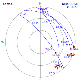
Satellites with 2 Meter Uplinks
Observations
Equipment
The primary radio receiver is a
Airspy
software defined radio (SDR)
with a four element
Yagi antenna
on a tripod. The antenna can be positioned in the
azimuth
and
altitude
directions to track the satellite across the sky.
Tracking a satellite is done manually by moving the antenna.
A second four element Yagi antenna was added with its own coax to the receiver. The receiver selects which antenna to use with a coax switch.
Two operating configurations are used. The first configuration is with one antenna positioned for the first half of the satellite pass and the second antenna positioned for the last half of the satellite pass. The receiver is switched between the two antennas at midpoint of the satellite pass.
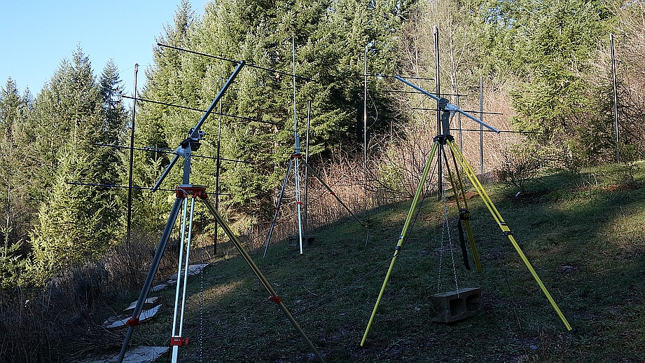
The second configuration as shown in the above photo is one four element Yagi antenna is positioned east at 30 degrees altitude and the second four element Yagi antenna is positioned west at 30 degrees altitude. This configuration is used for casual monitoring (lazy mode monitoring) of the satellites.
Also, the coax switch has three positions, two for the two different antennas and one position to a 50 ohm terminator. The 50 ohm terminator provides a quick check on which signals are internally generated from the receiving system and which signals are received from the antenna system.
Amateur Radio Satellites