Pierre has left us, but his legacy lives on in his myriad optical creations. This page will chronical the rebuilding of one of them-his motorized, 8" F/4 binocular chair. I happened onto it during one of the first SAC ATM meetings. A lot of Pierre's equipment and supplies were left behind. Some were brought to the metting for input on what to do with it. Someone was suggesting we split the optical tube assemblies into two 8" F/4 Dobs to be used as club scopes for newbies. I found this idea abhorent, so I volunteered to take it all home, evaluate its disposition and refurbish it if possible. I had a plan to install it in the rolloff roof of my Stone Haven Observatory, for use by visitors to star parties I regularly give. It's only been recently I've been able to find the time to look into the restoration. I believe I'll have most of the materials I need on hand, but some restoration of the building is now in order. More on that later. In the mean time, I'll take pictures of the chair in its present state and as it gets fixed. I'll also be entering the plans into a CAD program to document all dimensions and so on. I hope you're sitting comfortably...
The chair consists of four basic structures. The base, the azimuth box, the chair section and the optical tube assembly. This page will describe the chair section and subsequent pages will describe the other major parts. Hopefully, this arrangement will cut down on the load times for all the pictures I'll need to include.
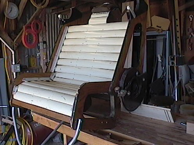
The chair portion looks rather like a lawn chair of some sort, with a few modifications. In front, is a footstool arrangement
that allows the user to step into the chair. In the bottom, in place of legs, are two altitude bearings that ride on the altitude
mounts on the AZ Box.
There is a large gear mounted behind the alt bearing on the left side of the chair that meshes with the altitude motor.
Above
the chair back are mounted two cradles for the optical tube assembly altitude bearings. These are more for raising the OTA so the
user can enter the chair, not for adjusting the aim of the OTAs. The user holds the remote control in their hands which controls
up/down, left/right motion. A full 360º rotation in azimuth is possible, but will not be recommended at SHO, because the unit will
be semipermanently wired in order to eliminate the battery. Side to side drift is eliminated in the chair by the gear on the left
side and two guides on the right, visible in the first photo as two white plastic squares screwed to the red alt bearing at ~100º separation.
The chair section weighs 75 lbs.
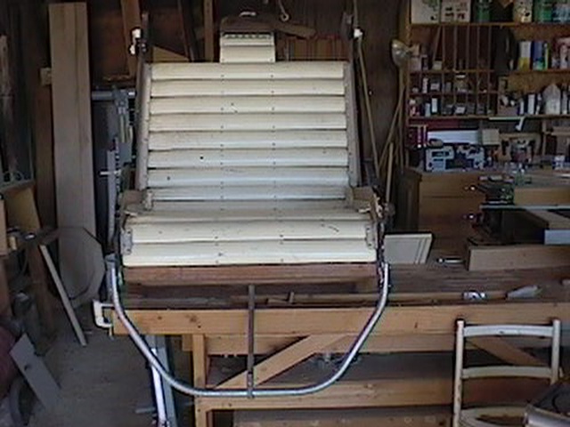 | Front view of the chair shows the unique slats that cushioned the body and the tubular step-up. Not much else is clear from here, though. The bottom of the headrest...? |
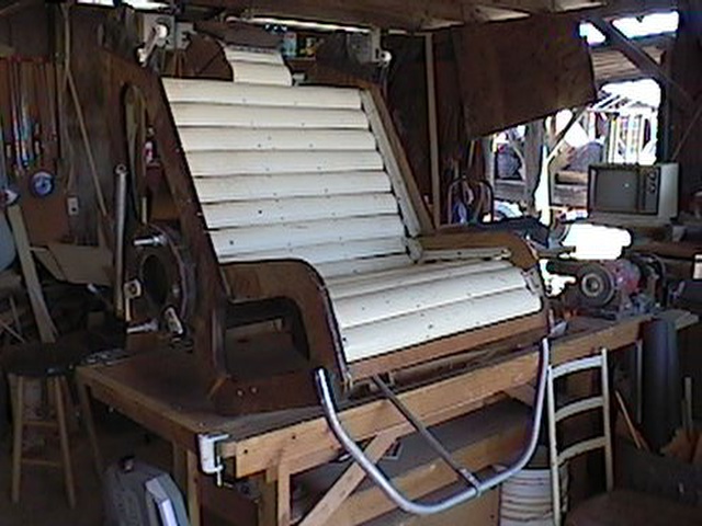 | Left side of the chair shows the red altitude bearing, the thrust bearings to keep it from wandering off the cradle, the spring for the OTA assembly, and the two bolts that held the battery shelf. |
 | Right side view shows the other alt bearing and something of the gear section and limit setting screw. Up top, you can see the cradle for the OTA, with its two rollers along the front edge. |
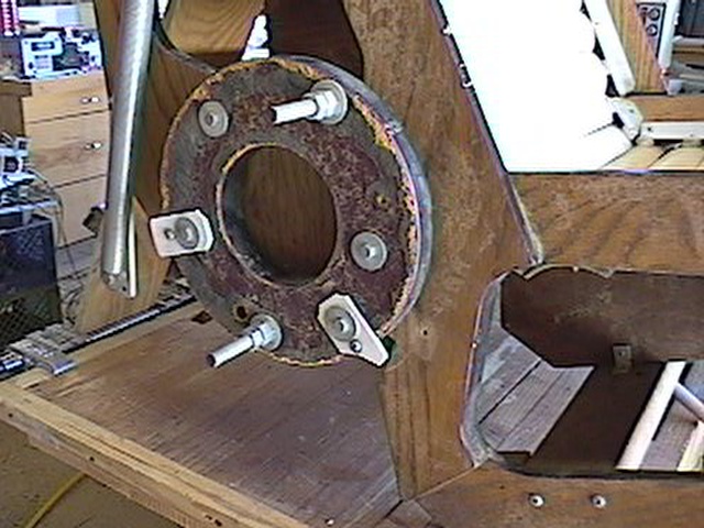 | View of the left side altitude bearing, showing the mounting bolts for the battery caddy, the alt bearing itself and the busted thrust bearings. To the left, you see the bottom mount for the OTA spring. I'll be removing this bearing to clean it up a bit, probably mount Ebony Star on the bearing surface and eliminate the battery caddy, since I'll be plugging this into a different power supply in the rolloff, although the battery arrangement does hold a certain attractiveness. |
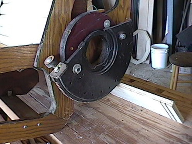 | Right side bearing and altitude
gear section. Same clean-up operation for the bearing. (As an aside, in the background you see the decagonal, 20" secondary rings for the 16" Split ring under developement for the SHO Dome. Too big for that scope, so if you need a set, let me know. We can work something out.) |
 | This is the altitude motor and right side
bearing assembly, as you would see it from the right side of the chair, if it was mounted. Also missing is the metal box that covered
it. (It's here, so don't worry. It's just not in the picture yet.) Also shown is the remote controller.
A good cleaning and greasing is all that's needed in the motor assembly itself, but the controller has one bad switch in it that has to be replaced. |
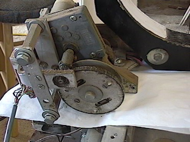 | A close-up of the alt motor assembly shows the gear reduction section and the controller connection. |
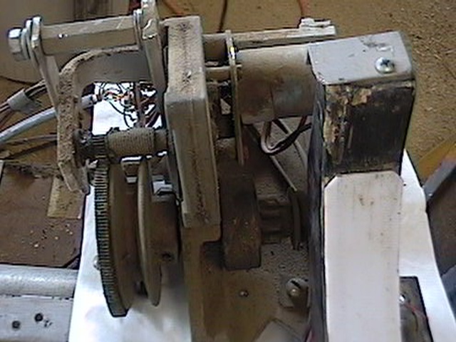 | This close-up shows the drive gear for the
altitude, the motor on the upper right, partially hidden by the cradle, and the gear reduction unit on the left. The need for a good
cleaning and regreasing is easily evident. I'm not sure if you can tell, but the teflon surface in the cradle is very thin indeed. It'll have to be replaced. |
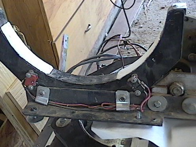 | Here's the inside edge of the right side cradle. Visible just under the cradle on the left is the altitude drive gear. Two limit switches are seen mounted to the underside of the cradle. The one on the right is clearly broken and will have to be replaced. This view also shows the thinness of the teflon. I'm not sure how thick it was to begin with, but it shows major signs of wear. |
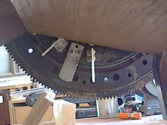 | The driven gear section from underneath the chair shows the aluminum thrust bearing between the two limit switch actuators. This looks good, and should work fine. |
The new, refurbished parts of the chair will be described here.