Pierre has left us, but his legacy lives on in his myriad optical creations. This page will chronical the rebuilding of one of them-his motorized, 8" F/4 binocular chair. I happened onto it during one of the first SAC ATM meetings. A lot of Pierre's equipment and supplies were left behind. Some were brought to the meeting for input on what to do with them. Someone was suggesting we split the optical tube assemblies into two 8" F/4 Dobs to be used as club scopes for newbies. I found this idea abhorent, so I volunteered to take it all home, evaluate its disposition and refurbish it if possible. I had a plan to install it in the rolloff roof of my Stone Haven Observatory, for use by visitors to star parties I regularly give. It's only been recently I've been able to find the time to look into the restoration. I believe I'll have most of the materials I need on hand, but some restoration of the observatory building is now in order. More on that later. In the mean time, I'll take pictures of the chair in its present state and as it gets fixed. Unfortunately, I started working on the chair before I had the idea to document the process, so I can't show everything before and after, but I started as soon as I thought of it. Most of the process will be here.I'll also be entering the plans into a CAD program to document all dimensions and so on. I hope you're sitting comfortably...
Here's the only picture I know of of the chair set up in a field. If anyone knows any salient details about this, please let me know!
The chair consists of four basic structures. The base, the azimuth box, the chair section and the optical tube assembly. This page will describe the base and the links will describe the other major parts. Hopefully, this arrangement will cut down on the load times for all the pictures I'll need to include. If not, I'll add more.
The base is a box 15" x 15.5" with 4, 4" diameter PVC feet at the corners that raise it
above the ground by 4". It has a central spindle of 2" diameter that serves as the azimuth axis. It has
a 14" diameter gear mounted horizontally that meshes with the azimuth drive gear which is mounted on the
azimuth box. The gear is raised 1/2" above the box by 4 metal spacers. The assembly weighs 33 pounds and has a low center of mass.
The main azimuth bearing is a 1/4" thick
phenolic sheet, cut in a circle 12" in diameter. Around the perimeter of this disk are 8, 2" diameter roller skate
wheels with bearings. The wheels carry the weight of everything above them and provide a nice, smooth ride.
Some cleaning is required, but no structural faults I can see. It should do fine as is.
The azimuth box is made of 2, 9" x9" x 9" cubes, connected along one plane by a horizontal section ~3" in height.
The final assembly is shaped somewhat like an inverted "U". It's made mostly of 3/4" plywood,
with one piece of 1/2" plywood mounted horizontally across the inside of the U. It was enclosed in the width
dimensions with 1/8" hardboard, with an interesting parque wood grain pattern printed on the surface. The same
pattern can be seen on the OTA's. The hardboard has split across the diagonal of one of the cubes, and the glue
between the horizontal member and inside vertical member failed, rendering the
box unstable and even dangerous. This section will have to be rebuilt from scratch. I intend to make it from 3/4",
furniture grade Baltic Birch plywood, and replace the hardboard with 1/8 Birch plywood, which I have onhand.
Mounted
in the low part of the U is the azimuth motor assembly. The unit is designed to easily turn the OTA, the az box and the occupant.
It runs on 12 Volts, supplied originally by a car battery mounted on a shelf in turn mounted on one side of the az box. Total
weight of the az box and motor is 61 lbs. The motor assembly is intact and works well except for one altitude limit switchbeing
broken and one azimuth directional switch on the remote control being bad. Cost to replace these items may run as high as $5 US.
The az box with motor weighs 61 lbs.
The chair portion looks rather like a lawn chair of some sort, with a few modifications. In front, is a footstool arrangement
that allows the user to step into the chair. In the bottom, in place of legs, are two altitude bearings that ride on the altitude
mounts on the AZ Box.
There is a large gear mounted behind the alt bearing on the left side of the chair that meshes with the altitude motor.
Above
the chair back are mounted two cradles for the optical tube assembly altitude bearings. These are more for raising the OTA so the
user can enter the chair, not for adjusting the aim of the OTAs. The user holds the remote control in their hands which controls
up/down, left/right motion. A full 360º rotation in azimuth is possible, but will not be recommended at SHO, because the unit will
be semipermanently wired in order to eliminate the battery. Side to side drift is eliminated in the chair by the gear on the left
side and two guides on the right, visible in the first photo as two white plastic squares screwed to the red alt bearing at ~100º separation.
The chair section weighs 75 lbs.
The OTA assembly consists of two 8" F/4 telescopes mounted in a rigid frame. Their light paths are collimated to meet between the tubes,
where a focussing mechanism focuses both images into a pair of binocular eyepieces. The original design had interchangeable 1.25" eyepieces,
but this arrangement has been abandoned, due to lack of eyepieces and a somewhat regretable unworkability of the interocular distance adjustment.
The binocular eyepieces were captured from a pair that had fallen on hard times. The interocular adjustment was preserved and seems to work
well. In a trial run last year, the arrangement worked quite well. Measurements will be taken of the ep's focal length, so magnification can
be calculated. Since the chair is meant for wide field scanning of large areas, it is not felt to be important to adjust the magnifiacation at
this time. I'm confident that when finished, the optics will be breathtaking on their own, without the need for more power in the future.
The OTA is connected mostly by garvity to the cahir assembly, but a spring it connected between the two to maintain tension no matter the
altitude of the objects being viewed. Measurements will be taken in this respect also, once the chair is returned to a safe operating condition.
Finally, there is an adjustment on the OTA that allows the user to change the height and angle of the head rest on the chair. I'm not sure
how well this functioned originally, but sometimes simple and ugly works better than high-tech. Maybe it's elegant, we'll just have to see. :-)
The OTA weighs 48 lbs.
Total chair weight close to 215 lbs.
So, on to the pictures descriptions, shall we?
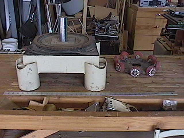 | Base and az bearing separated. There's a yard stick in front for scale. |
 | Oblique view of the base shows where the wheels of the bearing ride, just inside the main gear-sort of a "race", but not quite. |
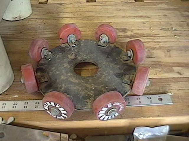 | Main Azimuth bearing. |
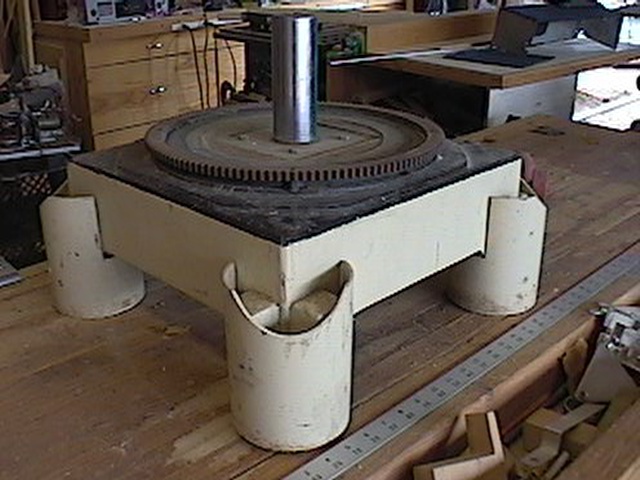
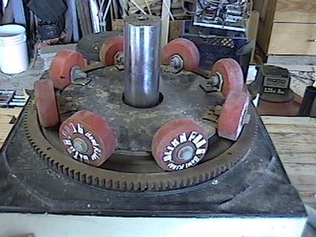 | Base assembly shows 2" "Spindle" for azimuth box. |
![]()
Copyright 2004, Steve Dodder
Webmaster: Steve Dodder
Created: 01/21/04
Last modified 01/21/04