Sorry about the poor picture quality, but I had to put something up. |
Pierre has left us, but his legacy lives on in his myriad optical creations. This page will chronical the rebuilding of one of them-his motorized, 8" F/4 binocular chair. I happened onto it during one of the first SAC ATM meetings. A lot of Pierre's equipment and supplies were left behind. Some were brought to the metting for input on what to do with it. Someone was suggesting we split the optical tube assemblies into two 8" F/4 Dobs to be used as club scopes for newbies. I found this idea abhorent, so I volunteered to take it all home, evaluate its disposition and refurbish it if possible. I had a plan to install it in the rolloff roof of my Stone Haven Observatory, for use by visitors to star parties I regularly give. It's only been recently I've been able to find the time to look into the restoration. I believe I'll have most of the materials I need on hand, but some restoration of the building is now in order. More on that later. In the mean time, I'll take pictures of the chair in its present state and as it gets fixed. I'll also be entering the plans into a CAD program to document all dimensions and so on. I hope you're sitting comfortably...
The chair consists of four basic structures. The base, the azimuth box, the chair section and the optical tube assembly. This page will describe the chair section and subsequent pages will describe the other major parts. Hopefully, this arrangement will cut down on the load times for all the pictures I'll need to include.
The chair portion looks rather like a lawn chair of some sort, with a few modifications. In front, is a footstool arrangement
that allows the user to step into the chair. In the bottom, in place of legs, are two altitude bearings that ride on the altitude
mounts on the AZ Box.
There is a large gear mounted behind the alt bearing on the left side of the chair that meshes with the altitude motor.
Above
the chair back are mounted two cradles for the optical tube assembly altitude bearings. These are more for raising the OTA so the
user can enter the chair, not for adjusting the aim of the OTAs. The user holds the remote control in their hands which controls
up/down, left/right motion. A full 360º rotation in azimuth is possible, but will not be recommended at SHO, because the unit will
be semipermanently wired in order to eliminate the battery. Side to side drift is eliminated in the chair by the gear on the left
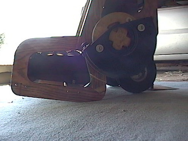
side and two guides on the right, visible in the first photo as two white plastic squares screwed to the red alt bearing at ~100º separation.
The chair section weighs 75 lbs.
 | As it turned out, the old altitude bearings, shown at rear,
were made from MDF or regular particle board. Absorption of moisture had swollen them at critical points, so I had to rebuild them. I used 2 layers of 3/4"
furniture grade birch plywood. Both layers were cut with the 4 spoke pattern you see and offset when glued to place the rear spokes within the front open areas
These are incredibly strong and combined with the careful glueing and 4 coats of polyurethan, should seal sufficiently to prevent this problem in the future.
This image shows one bearing completed whhile the other awaits polyurethane. Both were assembled and lathed together to assure they are identicle. The split half-round stock seen on the back of the unfinished new one and the old one on the right are used as spacers to set the distance between them. This had to change a bit, due to the new ones being thicker than the old ones. Both are edged with Ebony Star. |
 | The altitude cradle was structually sound, although the Teflon bearing surfaces were very thin. The new alt bearings are ever so slightly smaller in diameter, allowing me to use Easy-Glide pads for the new bearings. Easy-Glide pads are made for heavy furnture and are slightly thicker than the old Teflon when it was new. They slide nice and easy now. Maybe too easy, though. If I figure it out, I'll post it. |
 | This is a not-so-great shot of the chair with the seat material removed. It's made from a few 2x4's and 3/4 plywood. Everything was just fine with this part structurally. I just sanded it down and refinished it. I cleaned all the individual seat pieces. They were assembled in frames as subassemblies. Front of seat, seat, back and headrest. Each section was just PVC pipe, split lengthwise to yield a particular chord. Each piece of pipe |
 | One of the seat sections. You can see the aluminum framework and the portion of PVC pipe. |
 | text. |
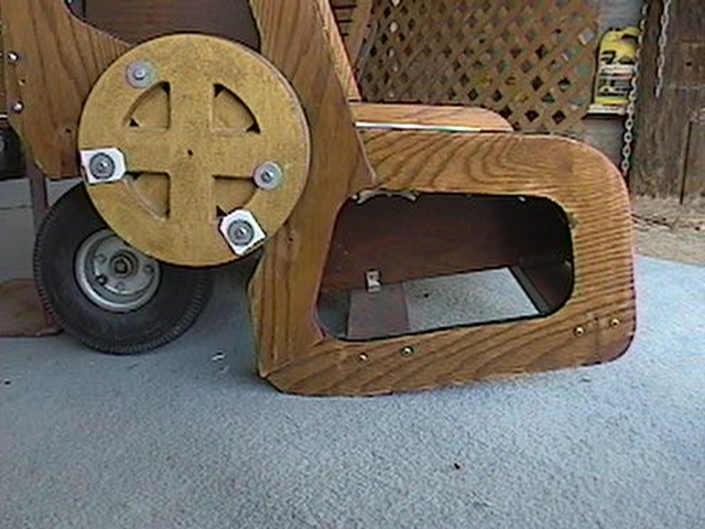 | The new altitude bearing shown installed on the right side of the chair. The plastic limiting strips are broken ans may be replaced by plywood ones. I'm not sure how much sideways movement the chair exhibits in operation, so I'm not sure if I'll need to replace these or not. Pierre felt they were necessary for some reason, so this is still under consideration. |
 | This shows the entire right side of the chair. |
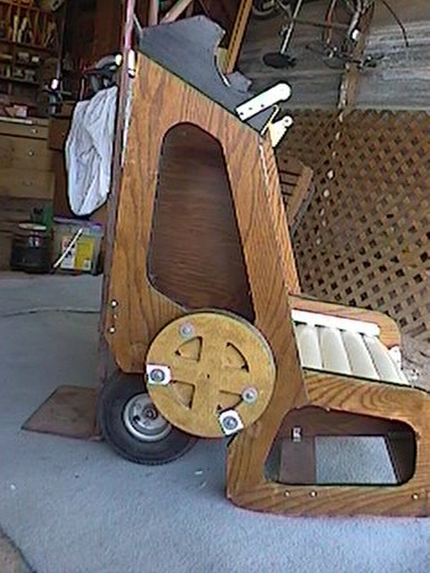
 | Here we see the left side of the chair with the new bearing and the altitude drive gear installed. |
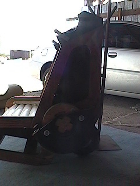 | Really bad shot of the left side of the chair. |
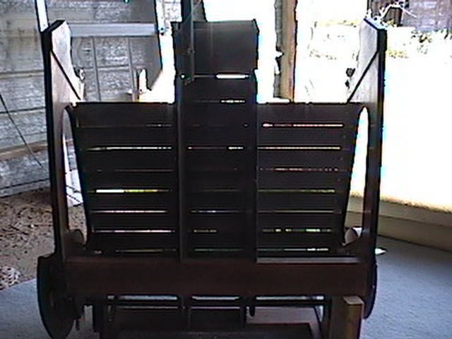 | Bad shot of the new chair fom behind. |
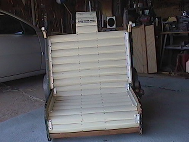 | Lovely image of the front of the chair. |
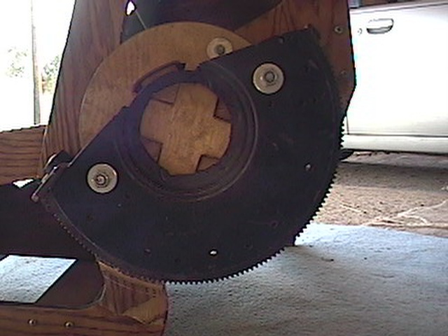 | Close-up of the altitude drive gear. You can see it's been stolen from a flywheel/starter gear of a vehicle of some kind. |
 | The structure under the chair. |
| text. |
| text. |