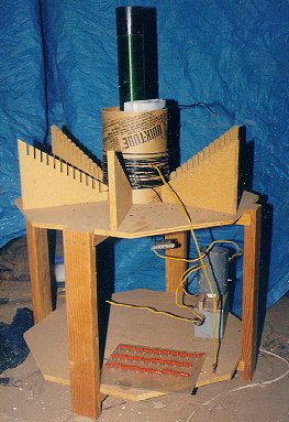
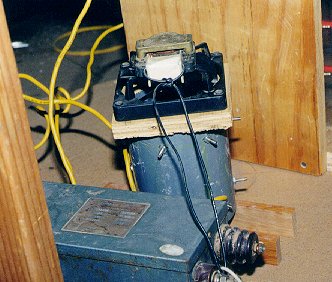
Note also the slick mounting for the capacitor on the bottom shelf.


|
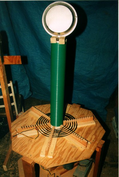
Here's the new, old coil, in the configuration I first got it to work. I think the real key was the new capacitor. While I remade the old type and installed it and it worked, there was a tremendous amount of corona around the plates and therefore wasted energy. I hadn't potted it in parafin yet, and while this makes a huge difference, I felt it was time to proceed into the future. The old cap was done to remove as many variables as possible in order to get the thing to work, and once it did, it was time to move on. You can see the new MMC just laying on the bottom shelf. The secondary is 3.5" PVC, wound with ~830' of #24 enamelled wire. The primary is ~20 turns of #10 copper wire wound on 8" sonotube and tapped at ~16 turns. Inside the sonotube, between the end of the primary and the secondary, you can see several layers of polyethylene plastic to prevent arcing. Unfortunate and ugly, but absolutely necessary as arcing here would roast the whole setup. The conical primary forms are obviously empty, since the original attempt with a copper tubing primary didn't work. I hope to return to this setup when the coil works better. Hopefully soon. |
|
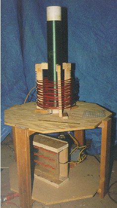
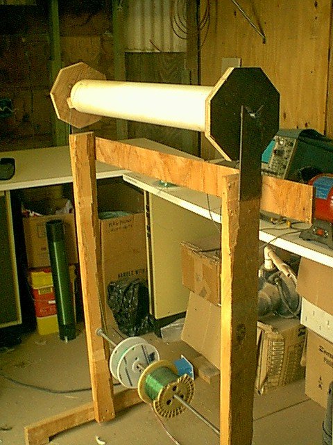
This shows the new coil in all its glory. Note the 6" x 6" wire mesh screen at right
and the brass rod in the center. Notice also the apparent connection of the primary forms to
the secondary. When I wound the primary on the new forms, they showed a tendency to pull the
forms to the middle, as the tension increased. I fashioned some blocks to fit between the top
of the forms and the primary to prevent this. There is no connection here! A
connection here would be disastrous! As it is, the coupling from primary to secondary is
too strong, causing a "cone" of corona to extend from the top of the primary to the secondary,
about 3/4 of the way to the top. Unsettling...
Note also the slick mounting for the capacitor on the bottom shelf. | |
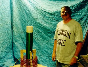
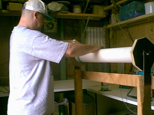
Me and the coil, for scale. I'm 6' tall. I'm holding the brass rod in my left hand. | |
Closeup of the MMC. This shows the modular nature a little bit. Most connections are made with the alligator clips shown, or will be. This makes it easier to change configurations. Once optimum performance is reached, I'll probably hardwire it. | |
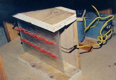
Closeup of the gaps and squelch fan. Unlike some schemes I've seen, each screw represents a single copper tubing element. There are then, two rows of gaps- one along the top the other below this and offset. The squelching by the fan works best when placed closest to the gaps being used, but sometimes there is arcing between the NST input and the body of the fan. This happens mostly when the coil is at higher power. Rerouting the power to the fan seems to fix this. I plan to add an RF line filter to this leg, too. | |
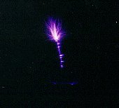
Two second exposure of the coil in action. Note the corona around the top turn of the secondary. | |
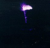
2 second exposure of the coil with Rosie pulling a spark off the output with the brass rod. Don't try this at home! These sparks are roughly 16" long. | |
Here's the 6" x 6" wire mesh placed on top of the coil form. Exposure time is 4 seconds. | |
This is a nice one. I just made a loop on the output wire. 4 seconds. Look at the corona around the top turn, though. All that energy is wasted. |
|
|
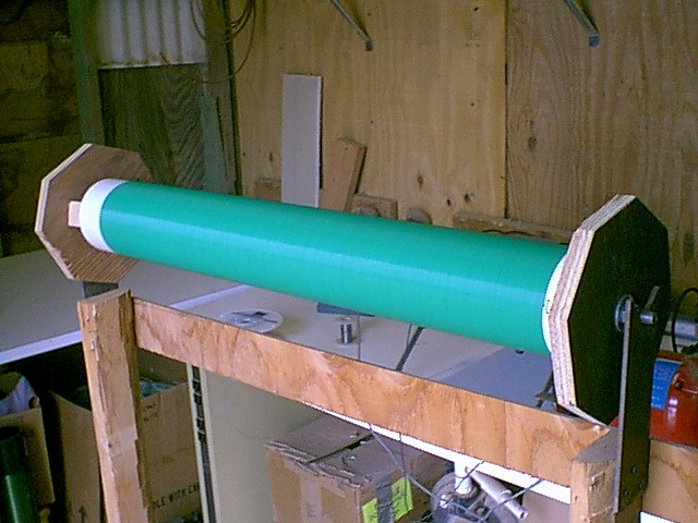
The new coil form on the winding jig just before winding begins. |
|
Here we go! Just got started windig. Actually, this coil only took about 1 hour to wind, so it wasn't bad. |
|
Finished! Not crazy about the shade of green, though... |
|
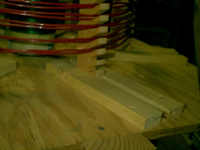
Here's a closeup of the adjustable primary form. It's a little fuzzy, but you can see the slots in the rails where pins go to keep it straight up and down. One of the pins is just visible above the first turns. There are always 2 pins in the notch in both vertical and flat configurations. |
|
|
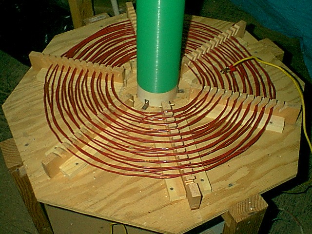
Nice picture of the whole primary. If you look close, you may be able to see some of the "taps"-points where the insulation has been removed. The alligator clip then clips here and sets the tuning. Since there are 2 turns per form notch, the clip is shown on the 10th turn. |
|
|
Here's a scanned image of the current configuration. The load on top is 2 9" pie pans screwed together. These are steel alloy and work really well, though I'm still working on a heating duct torroid. The primary is 10 turns of #10 wire wound flat, with 2 turns/ notch in the form. It's coupled only 1" from the secondary. This close coupling is a direct result of using Teflon insulated wire. |
| |
That's a bit better. This is about a 15 second exposure on 400 speed film and scanned in to a .jpg file. The top 1/3 of the sparks are cut off, since they're pretty faint for this camera, so the overall length of the sparks is well over 1 foot, and they "dance" around the pans, starting low and drifting higher, not unlike a "Jacob's Ladder" effect. Pretty spectacular! |
|
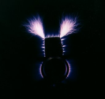
Here's one with the wire mesh stuck in the output load. Pretty cool, eh? Check out the corona around each element of the mesh. |
|
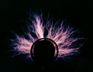
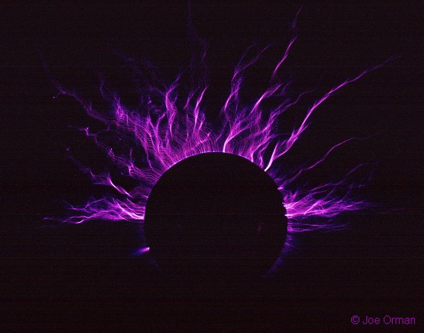
It takes a photographer to take a really good picture. This one is by my (all too modest) pal Joe Orman, taken during a visit on a cloudy night at Stone Haven. This is with the 9" pie pan output terminal. (I should mention, the coil was not working its best that night. It was soon after I diassembled and cleaned the gaps.) |
| Biography | Coil Theory | Pictures | My notes | External sites (links) | Main Tesla Page | Home |