It all started out a few months ago, when SAC had some ATM stuff donated, and an ATM group was proposed. It seemed several of the mirrors had older, scratched coatings on them and I was asked if I could strip them for possible recoating. I agreed, and was included on the email list. Pretty much nothing was done for several months. Then, Pierre Schwarr passed on and donated more stuff. Next, our treasurer got more stuff donated. Now, there seems to be a lot of stuff to be distributed, or worked on etc.
The first meeting of the group occurred on Tuesday October 17, 2000 at Thad Robosson's guitar repair shop. He had room for all the scope stuff, and agreed to hang onto it. Nine of us met there, fished around for what to do with the stuff. Finally, others ended up taking some of it home for reconditioning, or buying it outright for their own use. I did mostly the former, and some of the later.
Now, I find I am the holder of 2 6" mirror blanks, 2 5" mirror blanks, 2-6" mirrors of F/8.1 and F/4.4, (this one to be stripped and made into a solar scope, the F/8.1 is now assembled into a fine scope, but needs some refurbishment of the tube and a mount made), plus sundry other scope parts, tubes, diagonals and focusers. I also find myself reading up on mirror fabrication more seriously than before. I knew nearly nothing, just 2 days ago. Now, I know enough to seriously screw up any number of pieces of glass. :-)
This page will act as a chronical of my adventures in learning the ways of glass pushers. Fortunately, I will not face this road and its pitfalls alone. My partner will be the ever curious Sam, mentioned in the Tesla coil pages. He has rather a head start on me, having planned and summarily dropped an ATM project some months ago, due mostly to lack of funds and real life intervening. I have one picture so far of the materials on hand, with more to follow.
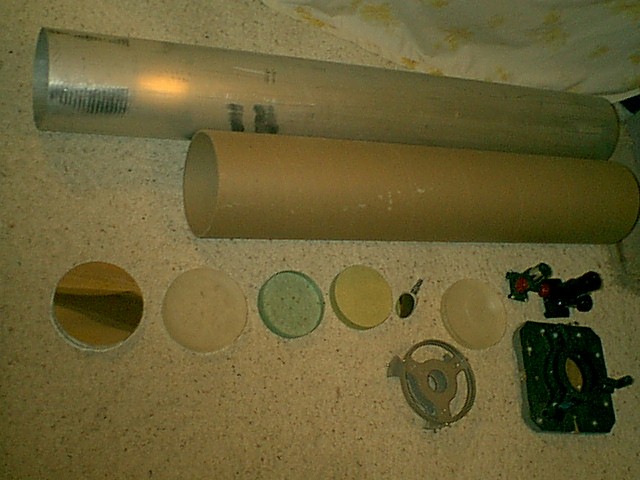
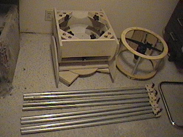
| Pretty crappy picture, but it's a start. | |
|
All the parts I brought home. Top: 49" aluminum tube, 7" diameter. Below: 39" Rolled paper tube, essentially sonotube, 7.25" diameter. Next row, from left: 6" F/4.4 mirror; 6" mirror blank; 2-5" mirror blanks; 1.5" secondary flat; 6" mirror blank; 2-1.25" focusers. Bottom right: 6" mirror cell and 8" mirror cell. |
|
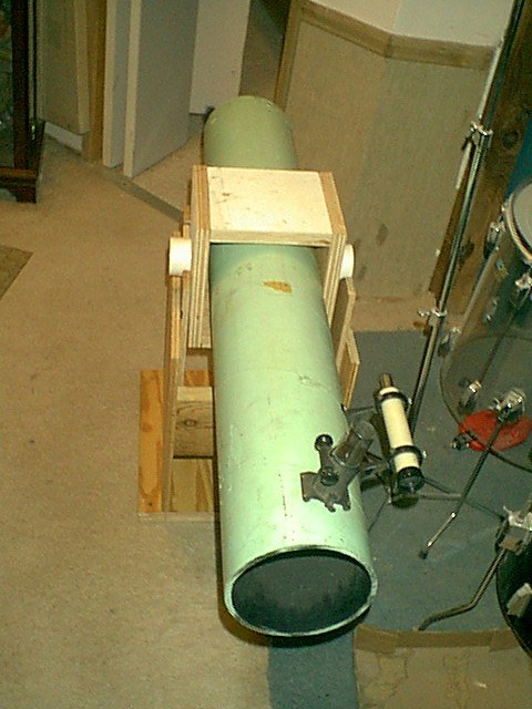
Here's most of the 6" F/8.1 scope I got. Basically, the OTA was complete, albeit "in a box", I just assembled it and built the Dob mount for it. |
|
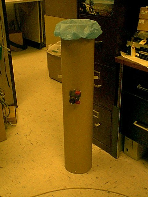
6" F/4.4 Solar scope. The OTA shown "complete" with high-tech dust cover. (99c shower cap) |
|
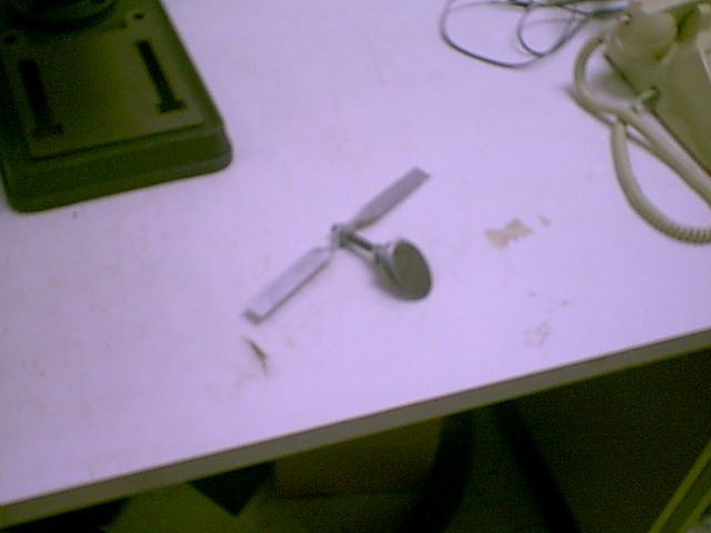
The diagonal, removed from the 6" F/4.4. I fashioned the "spider" from a piece of aluminum strap, twisted it in the center, drilled a hole and Presto! :-) |
|
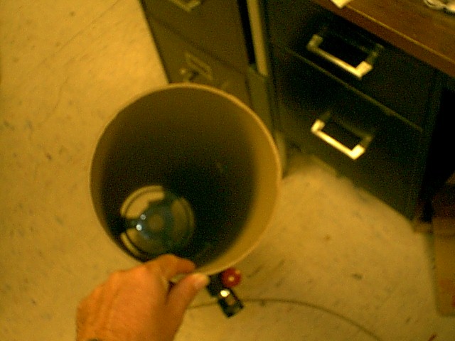
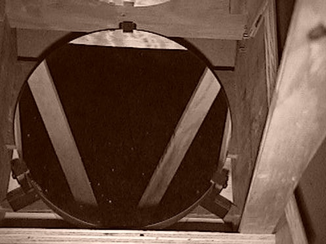
Looking down the tube with the secondary removed and... |
|
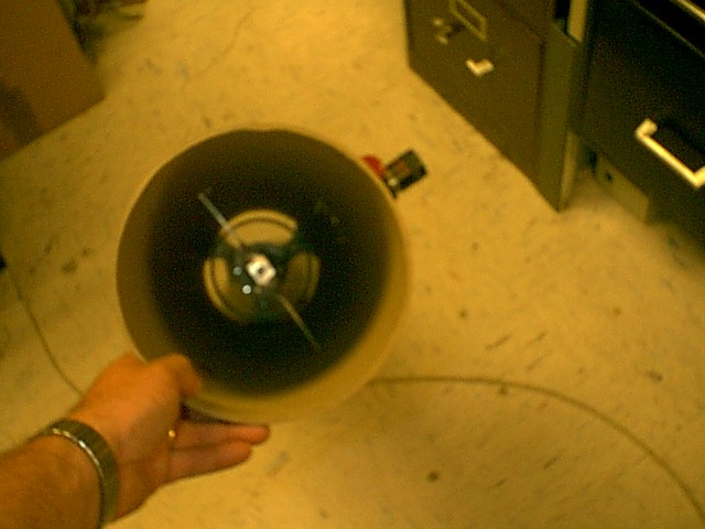
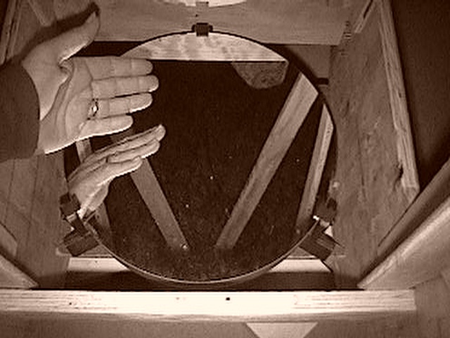
...installed. The full size pics are a little fuzzy, since that's my hand actually holding the tube so it won't reflect the flash, if you know what I mean. Tricky business, this "auto-photography"... heheh. |
So, I've begun to make actual instruments from the materials I snared. A little more practice, and some finishing techniques, and I should be able to present some nice stuff to the SAC for the public's use. Feels good, and bad, knowing the I can't keep first few scopes I make, but at the same time, using the experience gained on these to make the ones I do keep better. :-) Trade off, trade off...
Anyway, it's the beginning of the end, I'm sure. Since you should all know that, the surest sign of insanity is grinding your second mirror! Keep smiling!


The azimuth bearing is missing since I'll be mounting it on an equatorial Poncet (sp?) platform for tracking. More on this later. This one's gonna be sweet!
Here are some more pictures of parts of it, as of 12/31/01.
 |
|
 |
 |
| Figure 1 | Figure 2 | Figure 3 | Figure 4 |
 |
 |
 |
 |
| Figure 5 | Figure 6 | Figure 7 | Figure 8 |
 |
 |
||
| Figure 9 | Figure 10 | ||
 |
 |
 |
 |
| Figure 13 | Figure 14 | Figure 15 | Figure 16 | 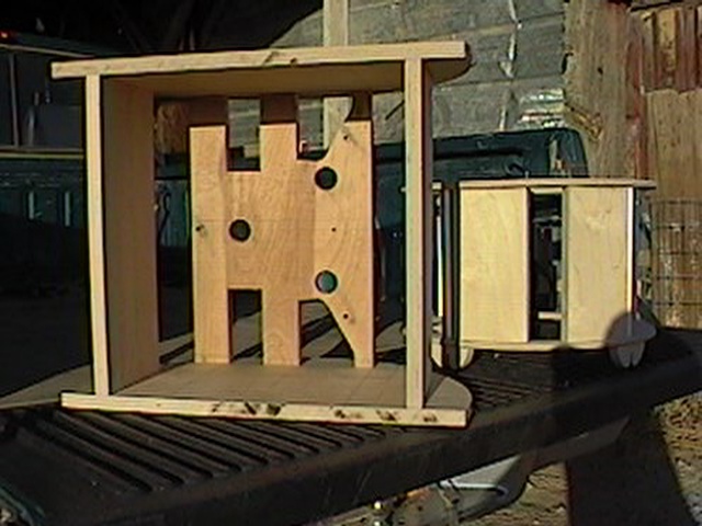 |
 |
 |
| Figure 17 | Figure 18 | Figure 19 |
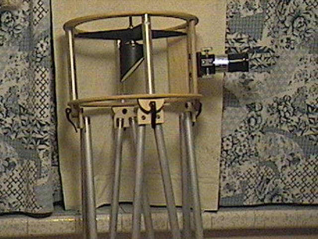
Figure 1 shows the secondary cage, focuser, spider and secondary assembly. The panel for the Telrad can just be seen on the other side of the tube, next to the focusser. Also visible are the clamps that hold the secondary cage to the trusses.
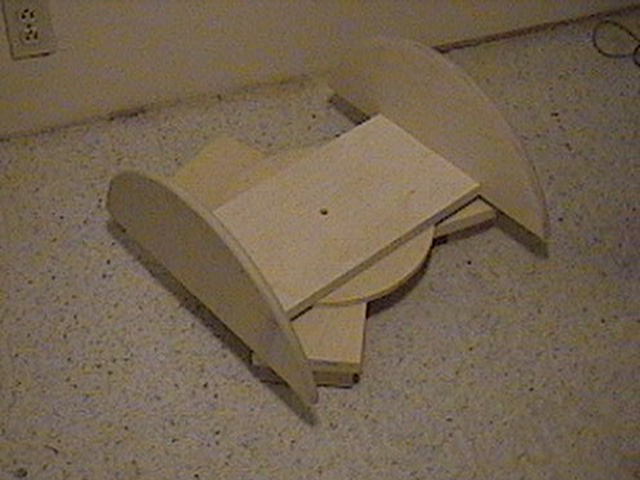
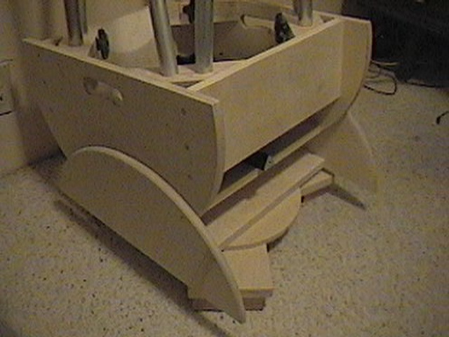
Figure 2 is the groundboard/azimuth bearing assembly. This allows use of the scope until the equatorial platform is designed and made. It's not quite finished here, but should be completed tonight or tomorrow. (3/5-6/02)
Figure 3 shows the mirror box placed on the groundboard aasembly.
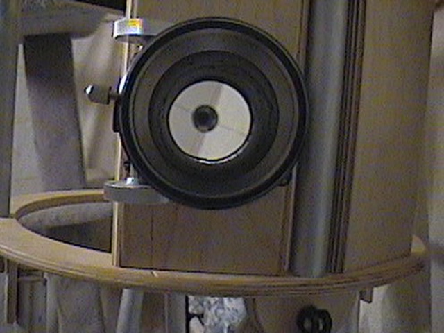
Figure 4 shows a view inside the mirror box. You can see the clamps on the inside corners, and the collimation mark at the center of the mirror.
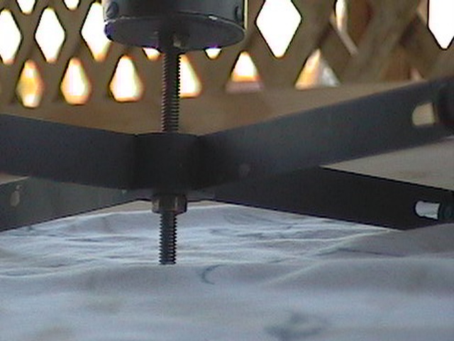
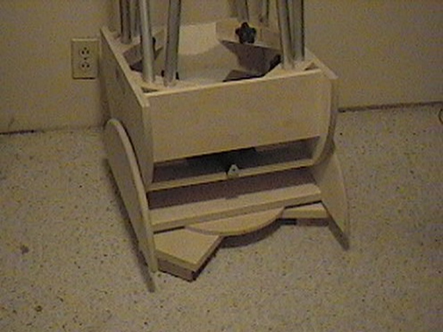
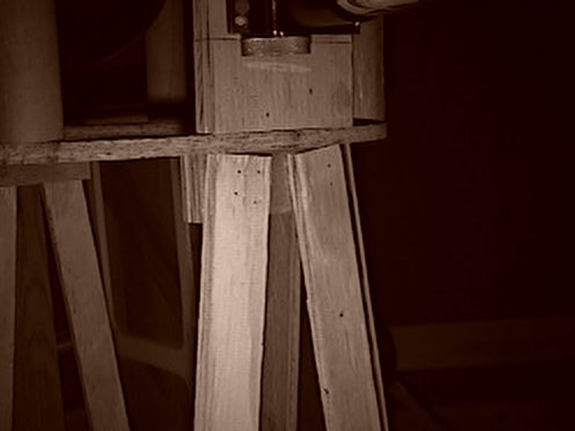
Figure 5 shows the middle of the optical tube strut assembly.
In Figure 6 the top is visible. The secondary cage is the only element that has the final linseed oil finish. This is a fairly good view.
Figure 7 is the mirror box from an angle, showing the handle cutouts.
Figure 8 is a view through the focusser. I had intended to show the collimation, but shutter "flinch" and auto focus in the camera kinda screwed it. >shrugs<
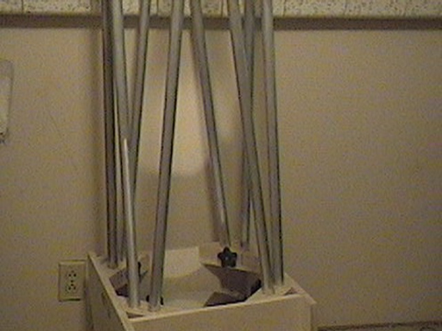
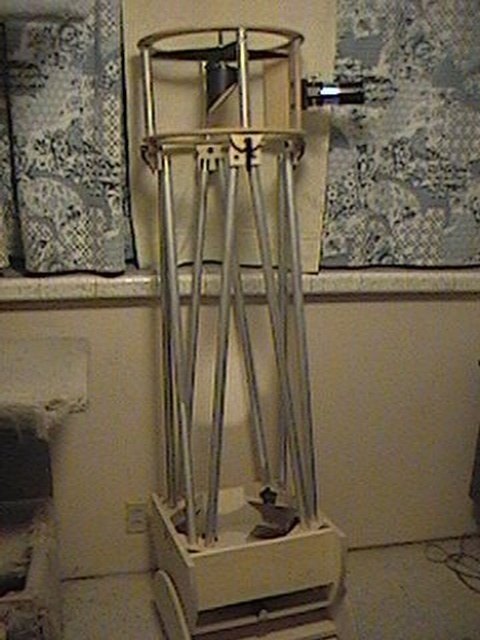
Figure 9 is the whole shebang.
Figure 10 is the whole shebang, 2 minutes later. It actually took linger to clear the debris for a clean shot than it did to disassemble the scope. :-)
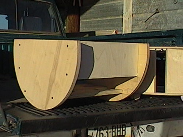
Figure 13 shows the mirror in the box.
Figure 14 and with my hand for scale.
Figure 15 closeup of the current prototype strut attachment to the cage. Note the plywood blocks behind the struts. This is similar in principal to the quick release setup for the finished model.
Figure 16 shows the mirror/rocker box in the foreground with the secondary cage in the back. The black screws will most likely turn into stanless steel in the finished project.
Figure 17 is a little wider view, with the rocker box turned on its side. This shows the mounting surface for the mirror cell and the trimming done to reduce weight. It also gives a better view of the secondary cage, with the two vertical panels for mounting the focusser and the Telrad or similar finder.
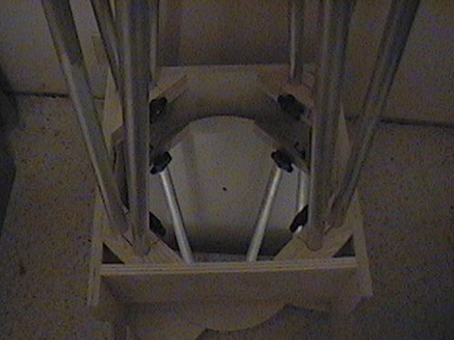
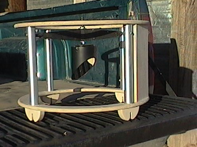
Figure 18 is a closeup of the secondary cage. It shows the mounting of the spider and secondary mirror, one of the panels, the mount for the tubes to the rocker box and the brushed aluminum tubes that separate the rings. The tubes are sealed with automotive car wax. Works great!
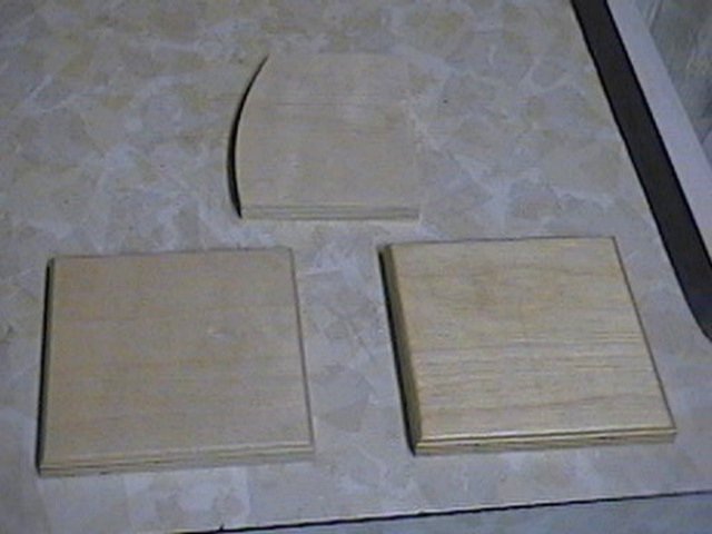
Figure 19 Shows the sample finishes for the wood. On the left is 2 coats of outdoor satin finish clear polyurethane. Not too shiny. It leaves the wood the same color and dries very tough. On the right is one coat of boiled linseed oil. Dries a tad yellow, compared to untreated, (top sample), but brings out the grain better than the polyurethane. Linseed oil also seals the wood and becomes rock hard and water proof after curing. (This is the same finish I have on my outdoor gate.) It's also easier to apply.