 |
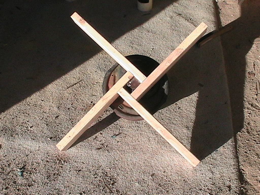
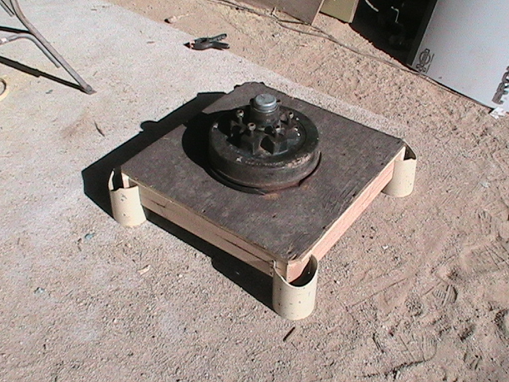
The basic base, showing the wheel mounted on 2x4's. |
 |
From the underside. |
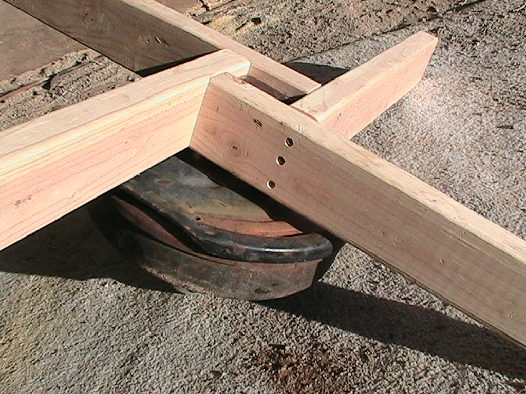 |
Detail shows screws, but glue was added later. |
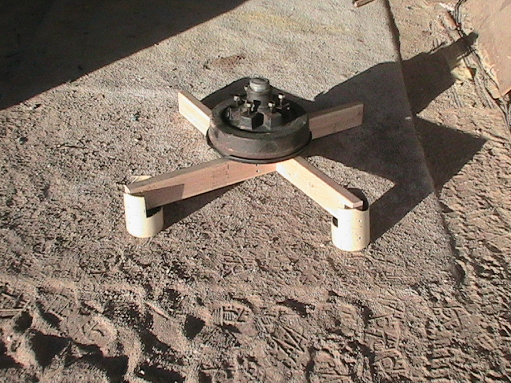 |
Illustrating the PVC "feet" to be used at the corners. |
 |
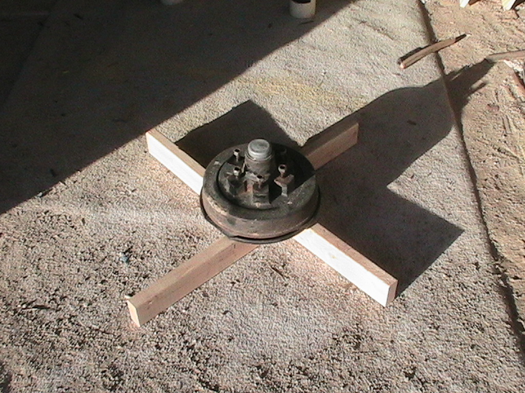
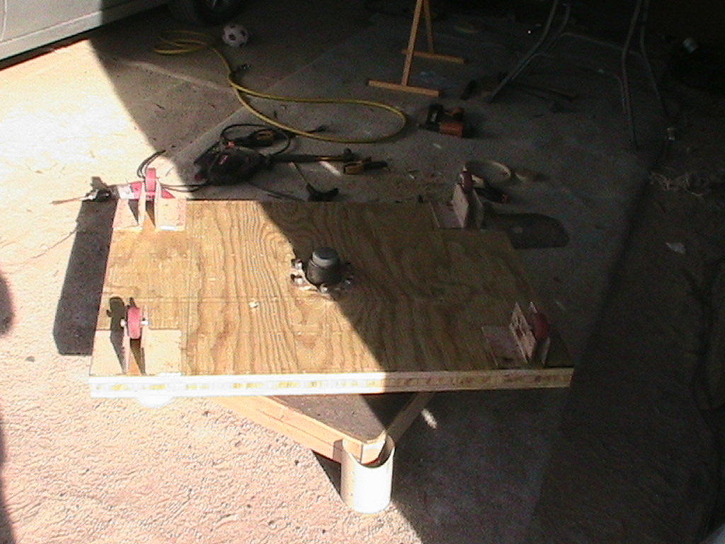
The (mostly) completed base unit. PVC feet are not yet attached, nor is the ring for azimuth drive cable. |
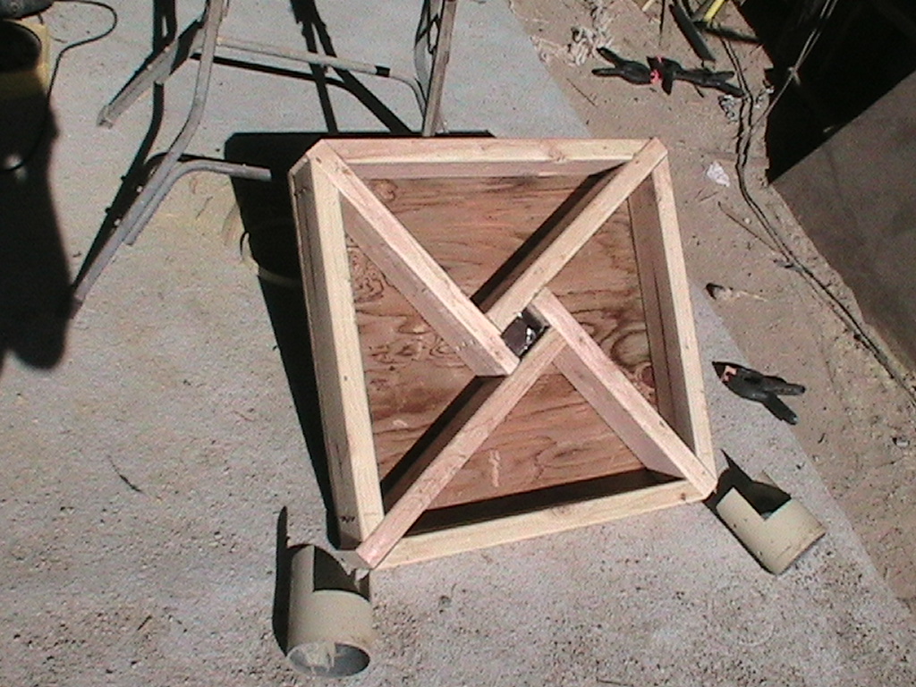 |
Structure from underneath. |
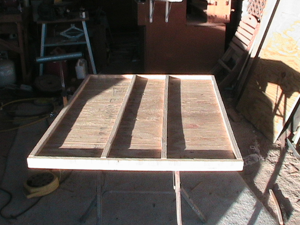 |
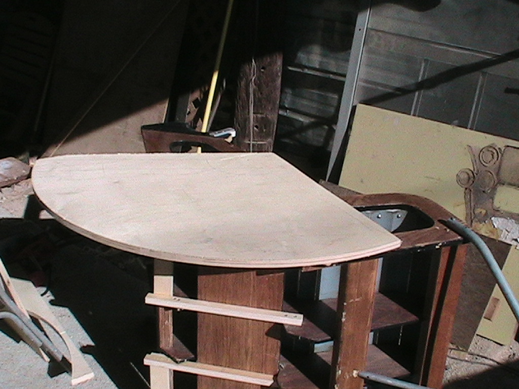
Beginnings of the torsion box to support the chair and OTA. |
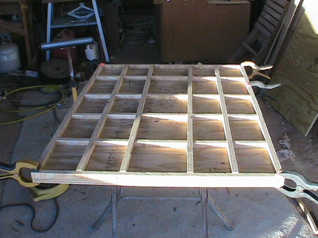 |
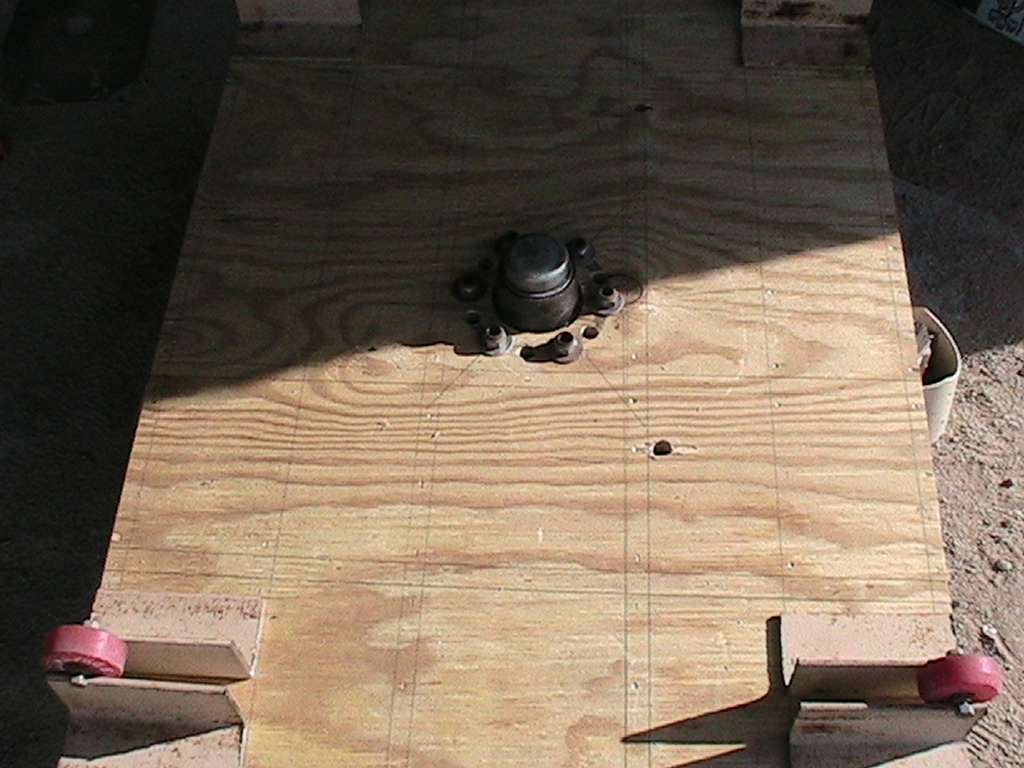
Good image showing the lower sheet of 3/4" playwood and the internal structure that lends the torsion box its strength. The strips are glued to the sheet, and glued to the top sheet, effectively connecting 25 smaller boxes of plywood together, rendering them very very stiff, yet not very thick. |
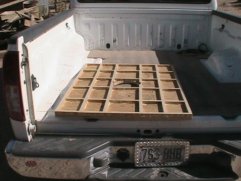 |
Bottom is glued and drying in the truck bed. |
 |
Each piece was glued and stapled to the bottom sheet to maintain position. |
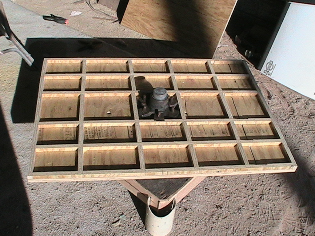 |
Bottom placed on pedestal assembly. |
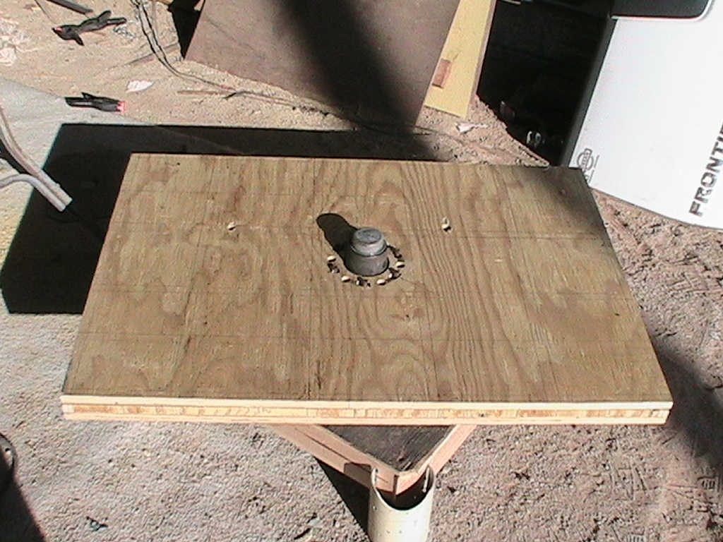 |
Top sheet placed before gluing. |
 |
Completed torsion box with rollers and steel brackets placed on top. |
 |
Thin! Rosie and I stood on opposite sides after this dried over night. We could detect no flexing or tilting at all. I weigh 213 lbs and she weighs...about half that. :-) |
 |
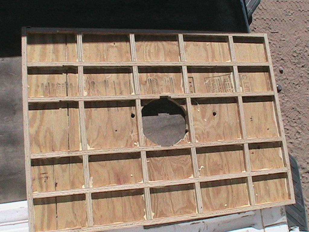
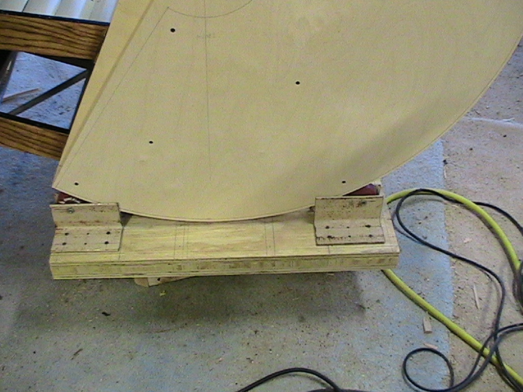
Close-up of the torsion box shows the staples and guide lines. |
 |
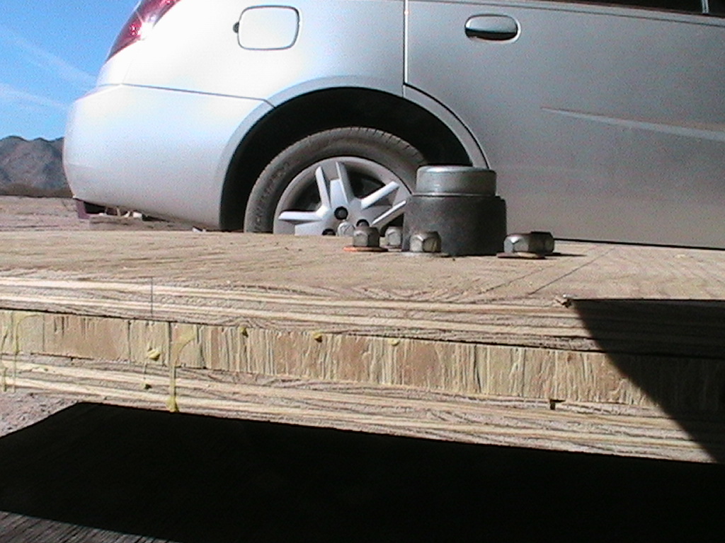
First rough cut of altitude bearing shows scale. Each bearing will be made of a 3/4" layer of plywood glued and screwed to a 1/2" layer, then trimmed to size. This is just the 3/4" slice.
|
 |
Clamped to the side of the cahir, without regard to center of rotation or mass. |
 |
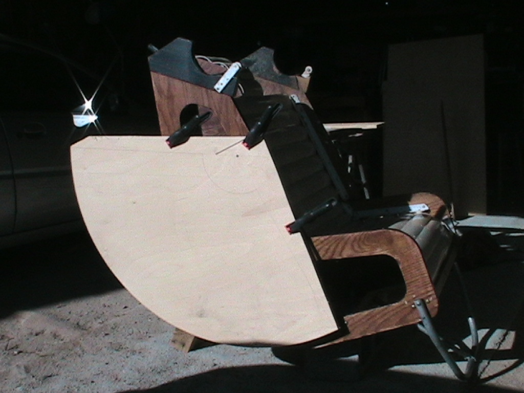
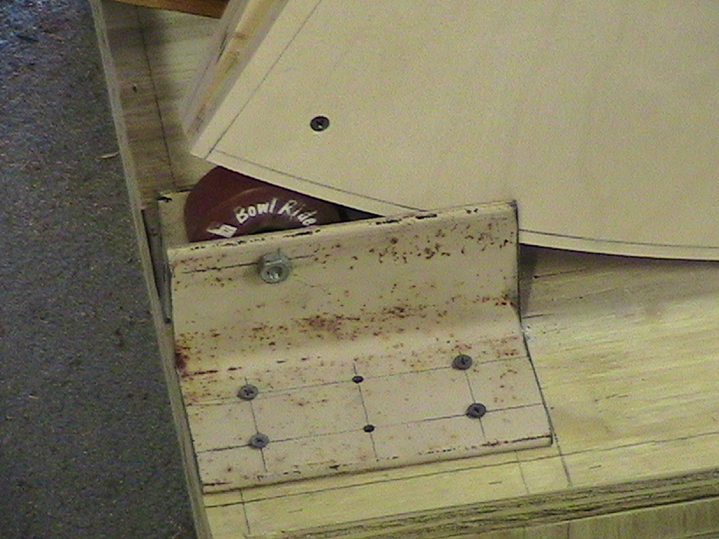
Final cut of the altitude bearings. Both layers are screwed together, and the final outline is visible on the side. Trimming will take place once final placement is made to ease location of center of rotation of the bearing. This shows the "calculated" center of mass, but it may change under further analysis. |
 |
Close-up of the chair sitting on the rollers for the altitude bearing. The steel angle iron is not quite wide enough between because the screws holding the roller wheels need to be slightly longer, so action is not as smooth as I'd like, but it's darn close! |
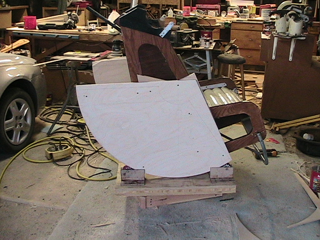 |
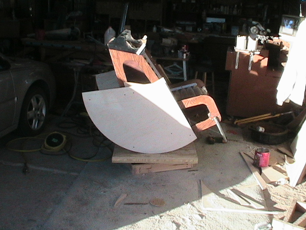
Wider shot of the chair on the base. |
 |
Close-up of the foreward portside roller. |
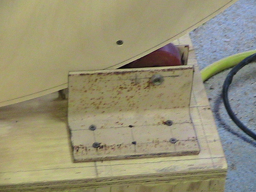 |
Portside aft roller. |
Fighting problems with a shifting center of gravity, I decided to rebuild the sides of the chair. The problems were
1) People are different.
2) The chair couldn't adapt to different conditions
3) The chair sides didn't have enough material to mount the rail solution.
4) The chair sides also had too many holes in them.
Different people have different distributions of doffering amounts of mass. As a more massive person sits in the chair, they shift the center of mass of the whole system. This causes balance and altitude motor loading problems as the load shifts. I came up with a couple solutions. One is to counter the shift by adding weights to the backside of the alt bearings, but this requires I carry many counterweights, and the whole idea was to avoid that. The one I chose was to make the chair and OTA adjustable foreward and backward, to reposition the center of rotation according to the weight of the occupant. I devised a system of T-rails, with bolts through the alt bearings. Two parallel rails will easily accommodate the load, but when I went to mount them on the chair, I found there wasn't enough material there to support them both. I took the chair apart to figure it out and, looking at the individual chair side and seeing all the previous holes, I decided to build new ones with sufficient mounting materials and consistant thickness.
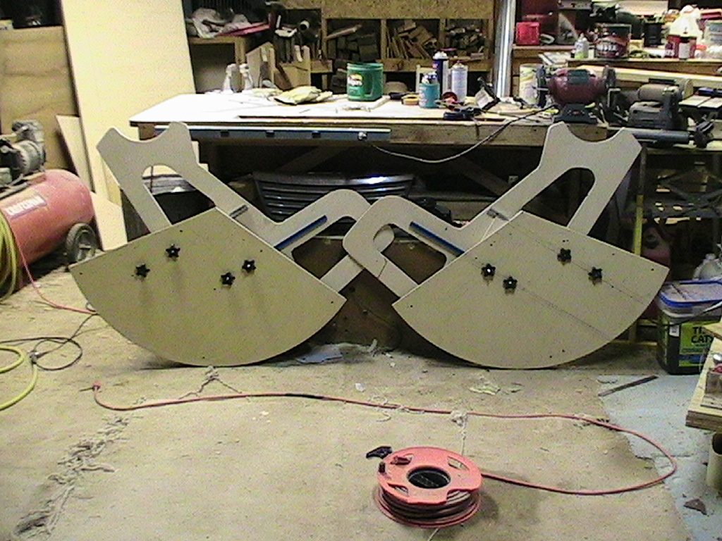 |
The new sides, side by side, ;-) showing the new bearings, the star-bolts that mount to the rails and fasten the bearings to the chair sides. |
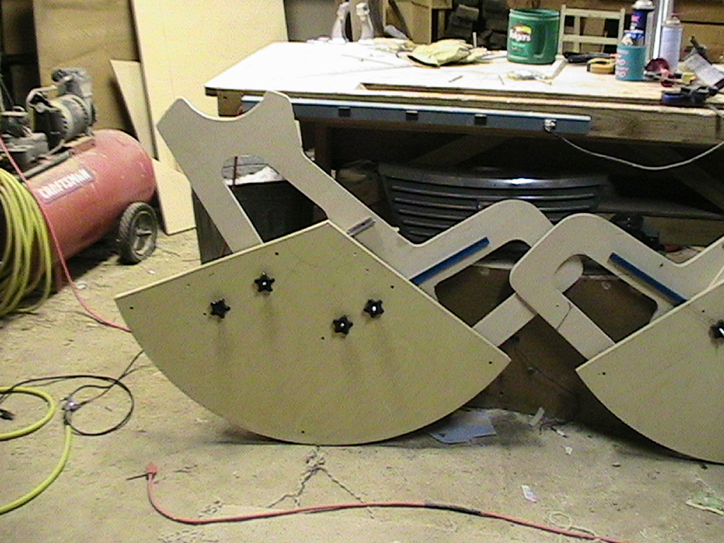 |
A little closer view of one new assembly. |